
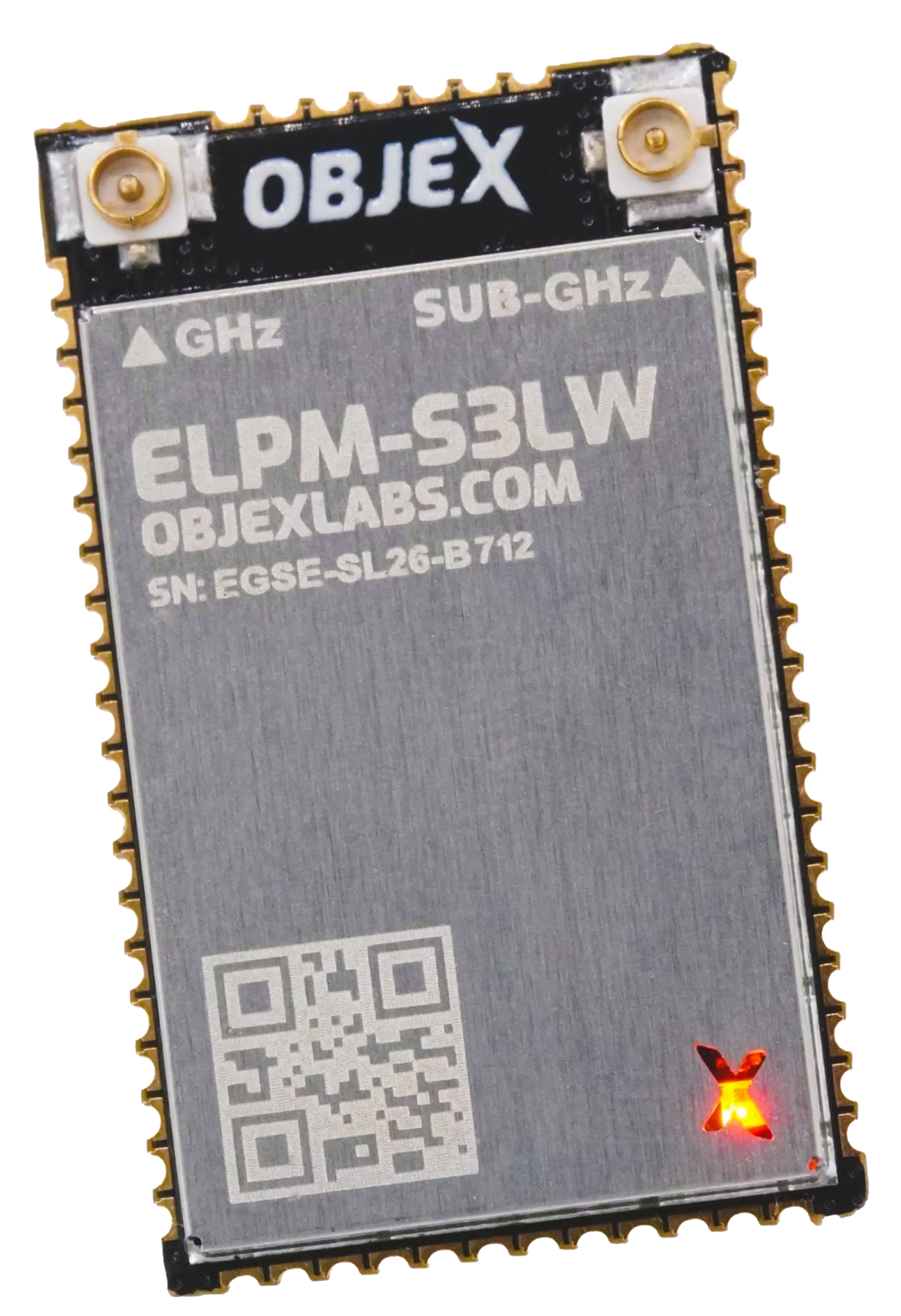
ELPM-S3LW
Built to switch off between events
Datasheet
CAD files
01 / Specifications
Every figure here is printed in the datasheet.
ELPM-S3LW is a power-managed ESP32-S3 and LoRa platform for intermittent IoT devices. A node can wait in Deep Stop, wake from an event or the RTC, process and transmit over LoRa, Wi-Fi or Bluetooth, then physically open its main supply rails until the next cycle.
Choose ELPM-S3LW when local processing and full firmware control matter, but the device spends almost all of its life waiting. Separate power paths let the designer choose what remains active and what switches off. Current units remain intended for evaluation, prototyping and integration testing until certification is complete.
Core
| Microcontroller | ESP32-S3FN8 (32-bit 240 MHz) |
|---|---|
| Flash | 8 MB |
| PSRAM | External PSRAM can be installed |
| WiFi | IEEE 802.11 b/g/n |
| Bluetooth LE | Bluetooth 5, Bluetooth mesh |
| Interfaces | I²C, I²S, SPI, UART, USB |
| Security | Cryptographic hardware acceleration |
| External RTC | RV-3028-C7 (45–100 nA) |
| Status LED | RGB WS2812B on GPIO48 |
| I²C pull-ups | Integrated, SDA GPIO8 and SCL GPIO9 |
Sub-GHz
| Transceiver | SX1262 |
|---|---|
| Frequency bands | 862 MHz to 928 MHz |
| Signal power | 22 dBm |
| Air data rate | 0.3 kbps to 62.5 kbps |
| Dissipation power | 1 W |
| Interface | SPI |
| Supply | Dedicated LDO2 3.3 V @ 300 mA |
| Antenna | 50 Ω U.FL / pad |
| Compatibility | LoRa and LoRaWAN |
Mechanical & certification
| Dimensions | 30 × 18 × 2.83 mm |
|---|---|
| Weight | 2.29 g |
| Certification | Pending release of the ELPM-S3LW version for mass production. |
Reference design / KiCad
Start your design from a KiCad-ready reference schematic.
Download the ELPM-S3LW v1.6 reference-design source files and adapt them to your application to speed up hardware integration.
Explore the four circuits and the LIS2DW12TR sensor nodePower traces / Otii
The bench recordings behind these numbers.
Energy calculator / Estimate
Turn a duty cycle into theoretical runtime.
Replace every assumption with measurements from your final device. The default Deep Stop current uses the documented upper limit of the RTC (100 nA); active-phase currents and durations are only a starting example, not guaranteed module specifications.
Ideal mathematical estimate. It excludes battery self-discharge and ageing, temperature, regulator efficiency, startup peaks, external sensors, retransmissions, radio link quality and minimum voltage threshold. Always verify the complete prototype with a power measurement.
02 / Why ELPM-S3LW
Wake. Measure. Transmit. Switch fully off.
ELPM-S3LW combines an ESP32-S3FN8, SX1262 LoRa, RTC and secure element in 30 × 18 mm. Its hardware power latch separates the short active phase from long waiting periods: 5 nA typical without the RTC and 80 nA typical with scheduled wake-up enabled.
Hardware power latch
A master latch with gate, wake and force-on inputs physically opens the rails instead of leaving the CPU asleep: 5 nA typical with the RTC disabled on the measured engineering samples.
Extreme low-power RTC
An external RV-3028-C7 draws 45–100 nA and provides multiple interrupt sources, so a scheduled wake-up does not require keeping the SoC alive.
Two radios, two bands
SX1262 for LoRa and LoRaWAN on the sub-GHz bands, plus the ESP32-S3 radio for WiFi 802.11 b/g/n and Bluetooth 5 with mesh.
Separated power paths
Dedicated LDOs for the SoC and for the LoRa section, a dedicated RTC supply pad, and a battery-level circuit with zero leakage current.
Edge-detecting inputs
A rising/falling edge detector and wake/gate inputs operate in the 1–30 nA range, so an external event can start the module from deep stop.
Castellated and solderable
61 castellated holes plus 8 ground pads on a 30 × 18 mm outline, with I²C, I²S, SPI, UART and USB brought out.
Typical applications
Where the device waits longer than it works.
Intermittent remote sensors
Take a small set of readings, process locally, transmit over LoRa and switch the rails off until the next cycle.
Event-driven monitoring
A contact, comparator or sensor interrupt wakes the system only when there is something to record.
Energy harvesting
Reduce the waiting load where energy arrives slowly and every active cycle must be budgeted.
Loggers & long-standby devices
The RTC starts scheduled acquisitions; Wi-Fi, Bluetooth or LoRa is used only during the active window.
FAQ
Questions, answered.
Is it certified?
Not yet. The units in circulation are engineering samples with no CE or FCC marking, and certification is tied to the release of the mass-production version. Use them for evaluation, prototyping and integration testing, not inside a product placed on the market.
Can I buy it right now?
Direct sales are suspended. Engineering samples and volume quotes go through info@objexlabs.com, and in the meantime the datasheet and the CAD sources at the top of the page are enough to freeze the footprint and start the integration.
Is it LoRaWAN compatible?
Yes. The SX1262 covers LoRa and LoRaWAN from 862 to 928 MHz, up to 22 dBm, with an air data rate between 0.3 and 62.5 kbps. It hangs off the ESP32-S3 over SPI and runs on its own LDO2 rail (3.3 V, 300 mA), and the RF path ends on a 50 Ω U.FL connector or on the antenna pad. The stack is your choice, any LoRaWAN library with an SX126x driver works.
How do I program it?
It behaves like any 240 MHz ESP32-S3 with 8 MB of flash, so ESP-IDF, PlatformIO, the Arduino core and MicroPython all work. Flashing goes over native USB or UART. USB, UART, SPI, I²C and I²S come out on the castellated holes, the I²C pull-ups are already on board (SDA on GPIO8, SCL on GPIO9) and the RGB WS2812B status LED sits on GPIO48.
What does nanoamp Deep Stop actually mean?
The power latch physically opens the main supply rails instead of leaving the SoC in deep sleep. On measured engineering samples, Deep Stop is typically 5 nA with the RTC disabled and 80 nA with the RTC enabled. The module wakes from an external event or, with the RV-3028-C7 powered, on a schedule. Complete-product consumption still depends on sensors, protection, supply design and duty cycle.